You Need Modelling Skills BRO!
Ok so a little skill might help but I’ll try and walk you through this intimidating kit. As usual if you missed the first look at everything that comes in the box, you can go to my previous post and catch yourself up with the ins and outs.
Moving forward in this post, I’ll begin construction of the Hobby Design JS Racing resin wide-body trans kit.
The end result of all of the exterior modifications bears this fruit. Let me show you how I go to this point.
Well it’s no secret that the glaring challenge in this kit is the one piece nose section. So I decided to tackle that right off the bat.
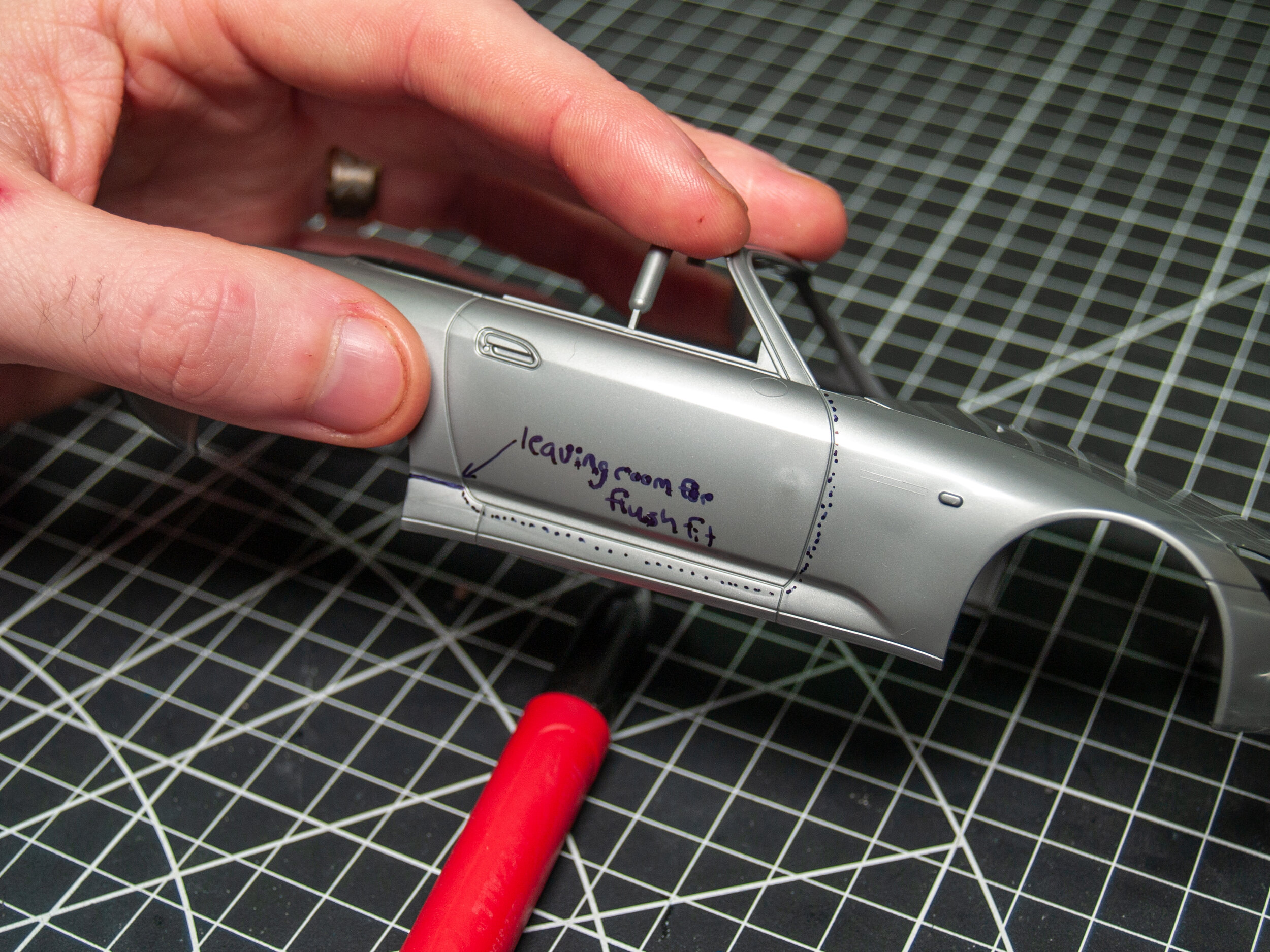
First, using the instructions as a suggestion, and not gospel, I outlined where the cut line would be. It seems to follow the door line all the way until it reaches the concave indent shown at the end of the arrow. Now because HD does not specifically show where the cut NEEDS to be made ( it’s really just a thick, dotted red line over that area), I’l leave some excess plastic there. when it comes time to dry fit, I’ll have a good buffer to slowly draw back until the two parts come together tightly.
First cuts made was using an RB Tools mini saw blade to made the separation between the window frame and the removal section.
The next series of cuts was sectioning off the straight section of delineation between the door and the side skirt. Less curves in the cuts makes for better final accuracy.
One of my favourite tools that is quite versatile when you experiment is the Hasegawa branded plastic scribing tool.
While being thinner than the tamiya version, it works great to follow a panel line that you need to cut along which creates a great guide trench when you come through with a saw blade.
When all of your cuts have been made through, the nose section should come straight off.
After all is said and done what you’ll be left with is the aft portion. You can see that I left some plastic on the rear portion of the skirts. The keen-eyed among you will also notice the excess plastic around the forward and bottom portion of the door. This is caused by the scriber cutting in a V shape. It also allows for there to be some final shaping between the joining parts to correct gap issues if there end up being any
As I mentioned in the previous post, The long tab in the middle of the door and the small tab ( visible between the clip and the end of the side skirt) ARE NOT to be removed. They are locating tabs. The mould tab on the backside of the side skirt in front of the rear wheel should be removed however.
You will also notice that area I was concerned with in the area where the rear quarter panel meets the side skirt has no gap. Each side was different so one cut equal on both sides would not work. Keep the extra and sand it back to get a better fit.
You may need to trim the tab and scrape some minor flash to get the nose piece to fit correctly. When you glue the skirt into place, take care to make sure the exterior surfaces are flush. This is important later when you install the nose and the rear flares.
Moving rearwards wit removal, the rear bumper was next to go. Again no clear instruction on where to cut was given and its expected that you assume you know what you’re doing. If you are unsure at the end then worry not. I cut right along the bumper and trunk line.
Again, leaving a little bit of plastic between where the cut needs to be and where you’re actually cutting helps prevent removing too much material and producing gaps.
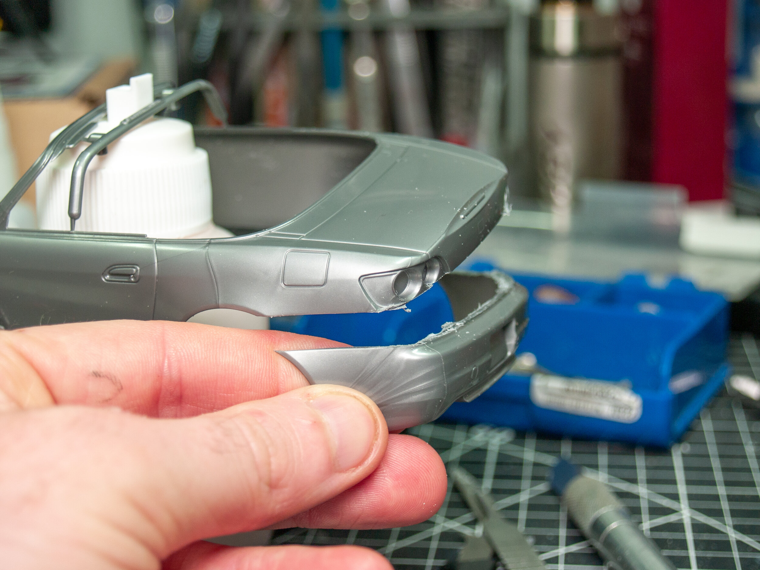
Once the bumper has been separated from the rest of the body, it makes it much easier to start removing the tail lights. The same procedure of cutting up to but not at the parting lines was used to make the cut accurate and reduce gaps.
The tail light on the right is the first stage of removal, with the excess plastic showing, and the tail light on the left is the final stage where a fine sanding stick or file can be used to bring it down to the final dimensions.
Like I said before, the internal structure of the tail lights is tricky. It’s a tight space and require some very fine removal to properly seat the HD aftermarket tail lights
Using diamond burrs instead of a more aggressive milling bit made removing smaller amounts of material very easy. In the above picture the left bucket has the internal structure still visible after the edging was cleaned up. After careful milling, you should end up with the bucket on the right.
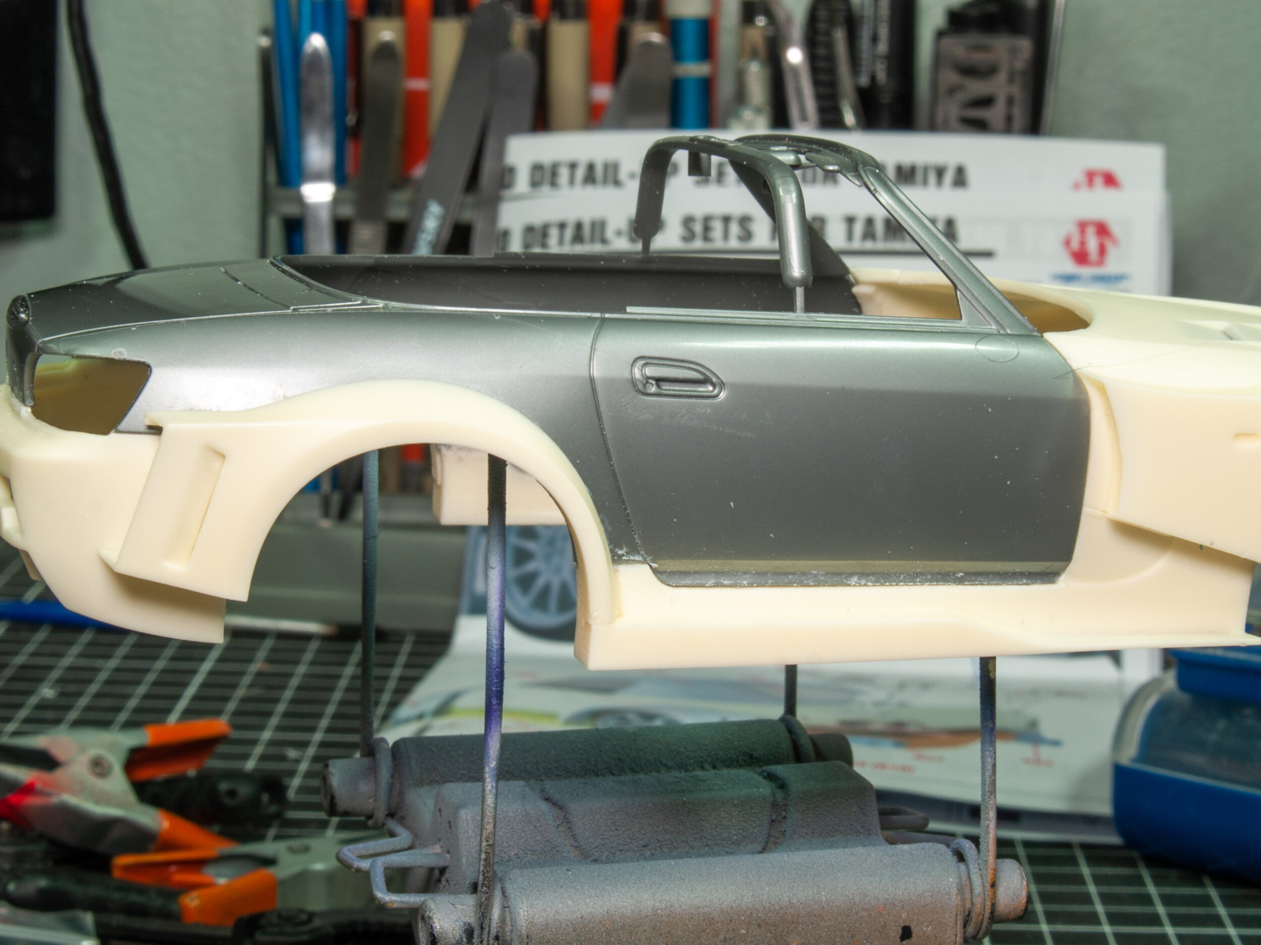
Next up on the list is the rear fender flares. After the removal and adjustment to the mounting points I attached it to the main body. Hobby Design makes it very easy to know if you have the flare in the correct position or not, though they don’t actually show you or notify you of the locating tabs on the skirts and the bumper.
Here you can see the two tabs that should remain in place to locate them into the rest of the kit. Any other extrusions should be removed and sanded flat.
Once that’s all sorted, it’s only a matter of clamping the flares to the body and gluing them into place
The final puzzle piece in this kit is the front end. As mentioned before, it’ all one section together and is a pretty integral part of the whole model. I chose to leave it until the very end. My theory behind that is because it can make or break the whole alignment of the body later on. Correcting the smaller pieces and their fit rather than dealing with a major twist from the get go seems to make sense in my mind. It may not have been necessary but always better safe than sorry.
The small dollar store clips are some of my most used tools on my workbench. The metal is ply-able enough to form the way I need but strong enough that the clamping force doesn’t deform them. They really clamp down so if the kit has a, softer plastic then they can mar the surface so be careful and be sure to test them first before going full bore on the actual kit.
That ends this portion of the build. You can see a compilation of the completed kit at this stage below. So far the only issues have been easily rectified and everything seems to align properly. All in all, a good kit so far at this stage. Next Ill be focusing on the brakes which are also a large focal point of this kit. I’ll see you all then.


